In this blog post, we learn how to configure Remote Access VPN with Cisco AnyConnect. The configuration steps are very straightforward, but there are many ways you can implement them such as
- SSL vs IPSec,
- full-tunnel vs split-tunnel, and
- -user account vs Radius/LDAP.
Our ultimate goal here is to provide remote users with a way to connect to internal applications securely while working remotely.
ASA Initial Configurations.

Since I created the topology in a lab, I’m using a private IP on the OUTSIDE interface. In the real world, that will most likely be a public IP address.
AnyConnect Full-Tunnel Configurations.
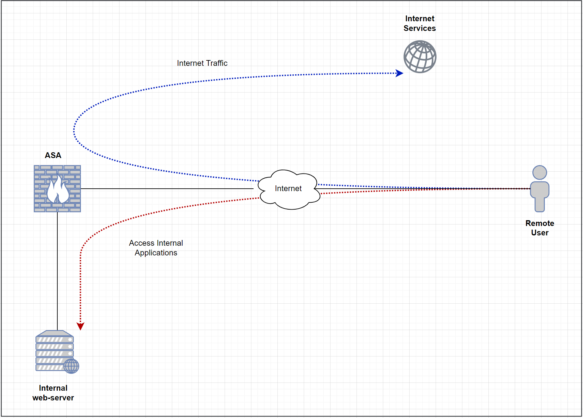
What does full-tunnel even mean? Well, with this deployment, all of the user traffic is sent to the ASA (including Internet traffic) and then Internet-based traffic breaks out to the Internet from the head office. The advantage of full-tunnel is that we can monitor and control the traffic that goes out to the Internet from corporate devices. Some of the downsides are increased latency and a high load on the ASA as all the traffic needs to traverse the firewall.
Full Tunnel Diagram
Step 1 - AnyConnect image
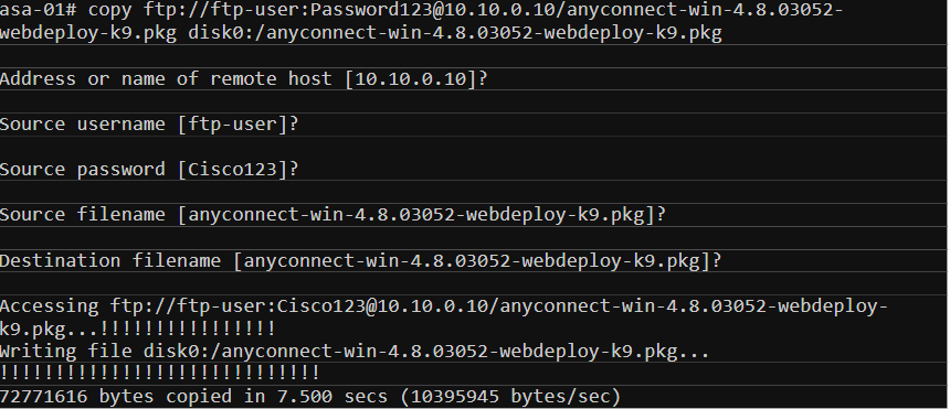
The first step is to upload the required images into the ASA. It is required to have the web-deploy AnyConnect images on the ASA so the remote users can download and install them on their machines.
Different packages are available for each Operating system. In this example, we use common packages to deploy (Windows, MAC, & Lunix for Android devices). The files can be downloaded from the Cisco website under support -> Downloads. I’m going to copy the images from an FTP server to the ASA. You can also uload them iva ASDM.
***Note: If you have HA deployment with two firewalls, you must upload images to both of them individually. The images are not synced across the HA deployment.
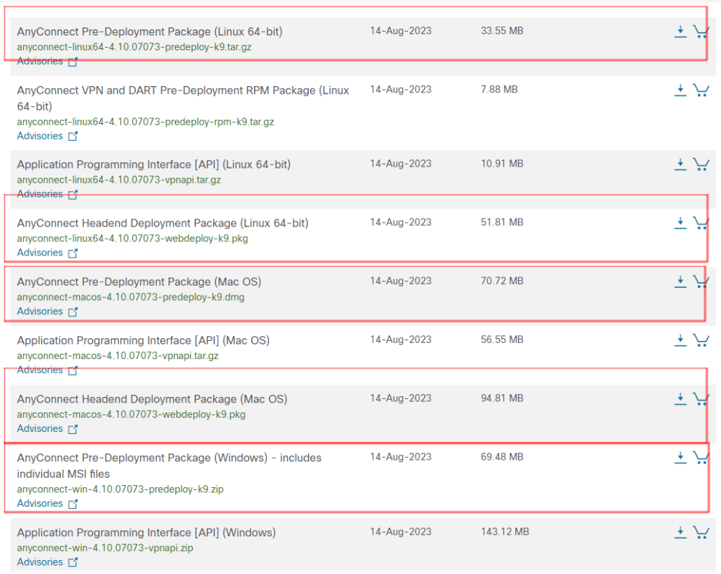
Headend Deployment Package vs Pre-Deployment Package
- Headend Package – The package can be uploaded into the ASA so the remote users can download and install it on their client machines.
- Pre-Deployment Package – This is the .exe executable file so the AnyConnect client can be installed manually on each machine (.dmg for macOS).

Step 2 - Create a pool of IP addresses
The next step is to define what IP range will be used for the AnyConnect clients. When the users are connected to the VPN, their laptops will receive an IP within this range. I’m also going to create an object which will later use in NAT and ACLs.

Step 3 - User accounts
For now, I’m going to use local user authentication. Later in this article, we can go through other options such as LDAP and Radius. I’m going to create a test user called anyconnect-user and set the service-type to remote-access.
***Note: if you don’t use AAA authorization for the admin login then all of the users configured on the ASA will be able to access the firewall (including the remote-access users).

With aaa authorization exec LOCAL configured, when the remote-access user tries to SSH into the ASA, the access is denied and a console message will be generated as shown below.
Step 4 - Configure Group Policy
Two of the core components of the AnyConnect VPN are group-policy and tunnel-group. Group policy is where we define parameters for the AnyConnect client to use such as DNS server, domain name and full/split-tunnel ACLs.
There are many other options available under group-policy to tune and tweak the login behaviour such as vpn-idle-timeout, vpn-session-timeout and vpn-simultaneous-logins.

Step 5 - Configure Tunnel-group
Let’s create a tunnel-group and bind the group-policy and the VPN pool we created earlier.

Step 6 - Enable webvpn
The next step is to enable webvpn in the OUTSIDE interface so, the ASA will start listening on port 443 and accepts the connection coming from the clients.

Step 7 - ACLs to allow the traffic.
I created an ACL to allow all the traffic coming from the AnyConnect VPN subnet as shown below. Please remember the ACL is applied to the OUTSIDE interface where the VPN terminates.

Step 8 - NAT rules
This is one of the most important (and confusing) steps, please refer to the diagram below.
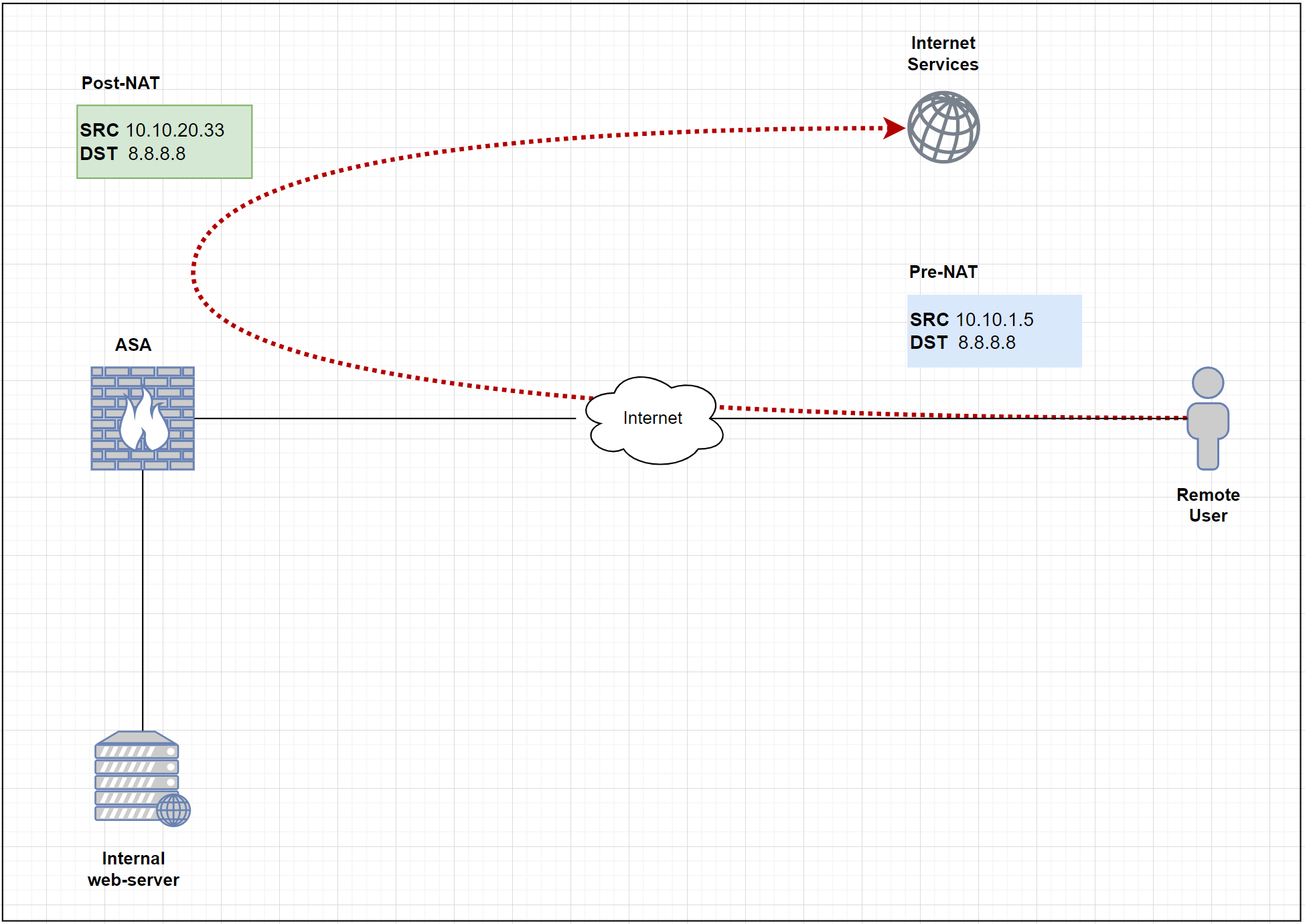
Since we are using a full-tunnel configuration, all the traffic has to traverse the ASA including the Internet traffic. In order for the Internet traffic to work properly, we must have a NAT policy on the ASA to translate the Source IP of the VPN traffic to the publicly routable address.

Step 9 - Hairpin / U-Turn Traffic
As we’ve seen in the previous step, Internet-bound traffic arrives and leaves on the same OUTSIDE interface. By default, this is not allowed and the traffic will be denied. So, we will need to allow the intra-interface traffic as shown below.
Verification and Testing
Now that we’ve completed all the required steps, it’s time for us to test. Let’s try and connect to the VPN and ping one of the internal servers 172.16.10.10 and 8.8.8.8
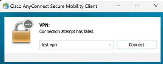

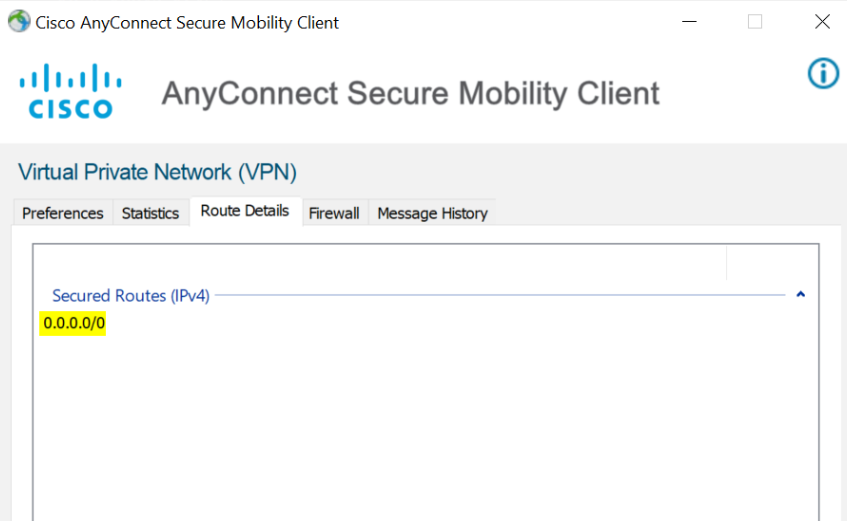
Sweet! As expected, we can see that the remote client can reach both internal and external resources. You can also see above that the ASA is pushing a default route back to the client (full-tunnel).
If you need more help with your network configuration, check out our page on network consulting for the other ways we can work with your business.

